Your Homemade Gadget Is a Tiny Radio Station (and the FCC Will Find Out)
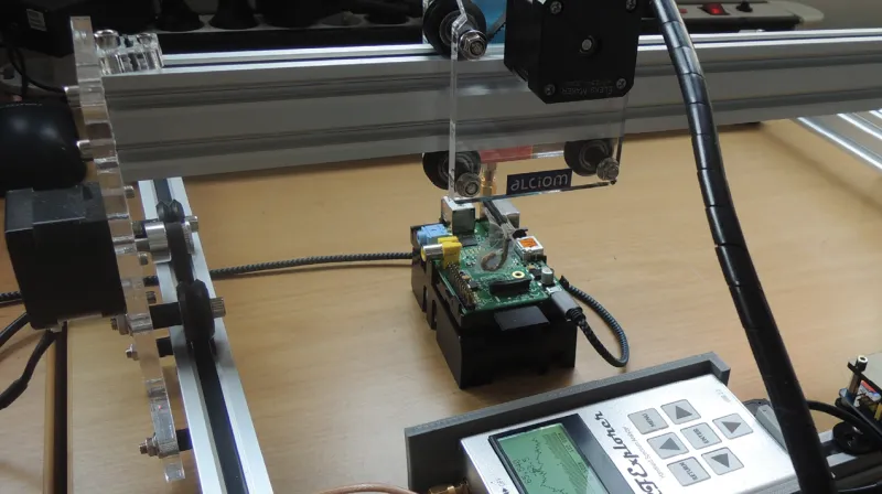
Photo: SDR dongle near field probe circuit board testing workshop, via circuitcellar.com
Somewhere in your shop right now, there's a microcontroller board happily broadcasting on frequencies it has no business touching. Maybe it's your smart garden controller, maybe the ESP32-based garage door monitor you've been meaning to finish. Either way, if it has a switching regulator and a clock running north of 8 MHz, it's transmitting — just not on purpose.
The good news: you don't need a $10,000 spectrum analyzer or a trip to an accredited lab to catch the worst offenders. We put together a working pre-compliance setup for $187, and it caught problems on every single project we scanned.
Why Bother Testing at Home?
If you're selling boards on Tindie or Etsy, FCC Part 15 rules apply to you, not just to the big players. Unintentional radiators — that's the official term for gear that isn't supposed to transmit — have strict limits on spurious emissions, mostly in the 30 MHz to 1 GHz range. A device that radiates too much can interfere with garage door openers, ham radio, aircraft navigation, and your neighbor's baby monitor. None of those are good outcomes.
Even if you never ship a unit, finding emissions problems early saves sanity. That intermittent I2C bus that drops out when the relay clicks? Often the same root cause as the radiation: sloppy return currents and unfiltered switching edges.
The $187 Test Bench
Here's the shopping list that got us started:
- RTL-SDR Blog V3 dongle — $35. This $35 software-defined radio covers 500 kHz to 1.7 GHz, which covers essentially the whole Part 15 band of interest.
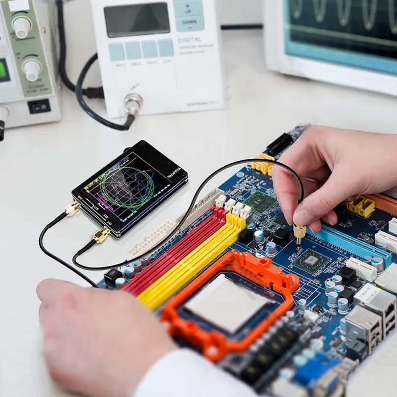
- A set of near-field probe kits (H-field loop and E-field stub) — $40 to $60, or about $8 in magnet wire and coax if you wind your own. We did both; the homemade loops work surprisingly well.
- A 20 dB preamp — $30. Near-field signals are weak, and the RTL-SDR's noise floor needs the help.
- SMA adapters, coax, a battery pack, and ferrite clamps — the remaining $60 or so.
For software, we ran SDR# (SDRSharp) on a beat-up ThinkPad and exported screenshots for comparison. If you want something more rigorous, the free version of Scanems or even a Python script with pyrtlsdr can log peak-hold sweeps over time.
One important honesty note: this is pre-compliance testing. Near-field probes tell you where the energy is coming from and let you compare before/after — they don't give you calibrated field-strength numbers. Think of it as a smoke detector, not a fire marshal's inspection.
Project One: The Noisy Garden Node
Our first victim was a solar-powered soil moisture node built around an ATmega328 and a cheap buck converter module. The scan lit up like a Christmas tree: a forest of spurs from 60 MHz to 300 MHz, all traceable to the converter's switching frequency around 100 kHz and its harmonics.
The fix cost about $2. A small ferrite bead on the converter's output, plus a 100 nF ceramic cap placed directly across the load, knocked the worst spurs down by more than 15 dB on the near-field probe. We also discovered the ground return from the converter was routed through a skinny trace that looped around the board — rerouting it shortened the antenna we'd accidentally built.
Project Two: The ESP32 Doorbell
Wi-Fi boards are trickier because they legitimately transmit. The trick is to test with the radio in standby and then with it active, so you can separate the intentional signal from the junk. Our doorbell board had a clean standby spectrum but a hairbrush of spurs when the Wi-Fi kicked in — the classic signature of a badly laid-out antenna feedline radiating harmonics.
Adding a small series resistor and improving the ground plane under the antenna trace cleaned things up noticeably. Did it fix our range problems too? Yep. Emissions and receiver sensitivity are two sides of the same coin.
Project Three: The Vintage Radio Restomod
Our restored 1962 tube radio got a modern Bluetooth module grafted in, and the 50/60 Hz hum riding the audio path was modulating the Bluetooth's own emissions into a splattering mess. A star ground topology and a proper LDO instead of a switching module for the audio section fixed it. Total cost: about $6 in parts and one evening of rework.
Before and After: What Improvement Looks Like
We keep before/after screenshots for all three projects, and the pattern is consistent: the biggest wins come from the cheapest fixes. Ferrite beads, decoupling caps placed properly, shorter return paths, and slower edge rates (many MCUs let you configure slew rate — use it) accounted for nearly all of the improvement. We never had to redesign a board.
When to Send It to a Real Lab
If you're selling more than a handful of units, budget for formal testing — a FCC Part 15 verification run at a lab typically runs $500 to $2,000 depending on the device class. But walking in with near-field scans and a list of already-fixed hotspots can cut retest cycles dramatically. Labs charge by the hour, and troubleshooting on your own bench is a lot cheaper than troubleshooting on theirs.
Build the Kit, Sleep Better
For under $200 and a weekend of tinkering, you get a permanent fixture for your lab that pays for itself the first time it catches a noisy regulator. And there's something deeply satisfying about watching your project's spurious emissions collapse in real time as you snap a ferrite on. Consider it one more instrument for the bench — and one less reason for the FCC to send you a letter.